From my previous Blog I announced that I was at the point of completion with Narellan. On that particular weekend I got to run some of the trains such as my Narellan runners and others that are part of my model rail collection that would be non-prototypical fit for this layout. I know, but my layout my rules.
However the Plan was to dismantle the layout, store it and get working on getting the other locomotives and rolling stock ready for the upcoming events for the year. Well, that did not get done at all. In fact, most of that week I was playing trains. And yes, it was fun and I guess well deserved time to enjoy running especially with the amount of work that I have put into it. But then I had to refocus in getting DCC Sound installs for some of my Locomotives for the following reason.
Narellan First Official Public Exhibition
After recently posting Narellan on a couple of Australian Model Rail Groups on Facebook attracted some positive interest to the point I was asked if Narellan can exhibited at the first Model Rail Exhibition for the year in the Sydney area with full details below found below.

DCC Sound Chipping An Austrains 30 Class Tank Engine That has Lights
Last year with the assistance from a good Model Rail Friend of mine walk me through on how best to install a DCC Sound Chip in an Austrains 30 Class (3025) which did not have lights. In that particular case, we removed the circuit board and did a hardwire configuration from the DCC Sound chip to the Motor. The removal of the Circuit board freed up space in the coal bunker portion of locomotive which allowed a Zimo MX684 Sound chip to be successfully installed. And indeed it was a tight fit for the Zimo DCC Sound chip. However, in the case of the 30 class tank Locomotives with Lights presents a different scenario altogether. Basically you need to keep the circuit board that is within the coal bunker as it contains the circuitry for the LED lights for the locomotive, or you will need to construct a more compressed circuit to allow for the lights to work which is indeed not simple for those that are not electronically competent.
What I am about to present is more my way of installing the DCC Sound as I'm sure that there are other methods that could be adopted that may work better. The method I'm about to show is more the easiest way to achieve a DCC Sound Chip install. But in saying this, it you are not competent in using a soldering iron or can grasp basic to medium soldering work, then my advise would be to engage someone who does have the competence, perhaps more someone who is in the business in the supply and installation of DCC chips.


Well some more DCC Chipped Locomotives ready to put on their first public at the Forestville Model Railway Exhibition. Hope to see you there.
However the Plan was to dismantle the layout, store it and get working on getting the other locomotives and rolling stock ready for the upcoming events for the year. Well, that did not get done at all. In fact, most of that week I was playing trains. And yes, it was fun and I guess well deserved time to enjoy running especially with the amount of work that I have put into it. But then I had to refocus in getting DCC Sound installs for some of my Locomotives for the following reason.
Narellan First Official Public Exhibition
After recently posting Narellan on a couple of Australian Model Rail Groups on Facebook attracted some positive interest to the point I was asked if Narellan can exhibited at the first Model Rail Exhibition for the year in the Sydney area with full details below found below.

DCC Sound Chipping An Austrains 30 Class Tank Engine That has Lights
Last year with the assistance from a good Model Rail Friend of mine walk me through on how best to install a DCC Sound Chip in an Austrains 30 Class (3025) which did not have lights. In that particular case, we removed the circuit board and did a hardwire configuration from the DCC Sound chip to the Motor. The removal of the Circuit board freed up space in the coal bunker portion of locomotive which allowed a Zimo MX684 Sound chip to be successfully installed. And indeed it was a tight fit for the Zimo DCC Sound chip. However, in the case of the 30 class tank Locomotives with Lights presents a different scenario altogether. Basically you need to keep the circuit board that is within the coal bunker as it contains the circuitry for the LED lights for the locomotive, or you will need to construct a more compressed circuit to allow for the lights to work which is indeed not simple for those that are not electronically competent.
What I am about to present is more my way of installing the DCC Sound as I'm sure that there are other methods that could be adopted that may work better. The method I'm about to show is more the easiest way to achieve a DCC Sound Chip install. But in saying this, it you are not competent in using a soldering iron or can grasp basic to medium soldering work, then my advise would be to engage someone who does have the competence, perhaps more someone who is in the business in the supply and installation of DCC chips.

Austrains 3136 before removing it from its box. Ensure that you test your locomotives before chipping to make sure they work. DCC chipping your locomotives in most cases can void any warranty.

For 30 class Tank Locomotives that have lighting, will have cab detail that is attached both to the Cab and the coal bunker parts of the locomotive.

To remove the coal bunker from the chassis, there are two screws to remove. These are the small screws that are located below the coal bunker.


The above two pictures shows the back and front of the circuit board. You will notice the plug for the 8 pin adaptor for a DCC Chip.

I tested out the DCC chip before undergoing the hard soldering the wiring from the DCC Chip to the female 8 pin plug

At the back of the Circuit board there are 2 x black wires that feed power to the rear LED light. It is best to unsolder this wiring from the Circuit Board as later on you will need to cut out a section of the coal bunker casting to allow for the DCC Chip to fit inside the cabinet of the locomotive.

Before unsoldering of the rear LED light wiring, as both wires are black, I labelled them to identify which was left and right when they needed to be soldered back on later on.

Basically I had to remove the cab and coal bunker away from the model for two reason, to prevent the my cutting tool (in this case a Dremel) not to have the main body work of the model get in the way and get damaged. The second reason to prevent the metal shavings getting sprayed over the locomotive. It is also worth noting that I did put a couple of wood dowels inside the coal bunker to protect the wiring and back section during the cutting process.

I gave just over 2 cm of wire between the chip to the Circuit to Hardwire solder into the 8 Pin plug on the Circuit board. The purple Wires (which is for the speaker) was kept at a long length. The wiring for the rear lighting was also soldered back in.
From here I reattached the coal bunker and Cab to back the Locomotive. All tested positive.
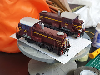
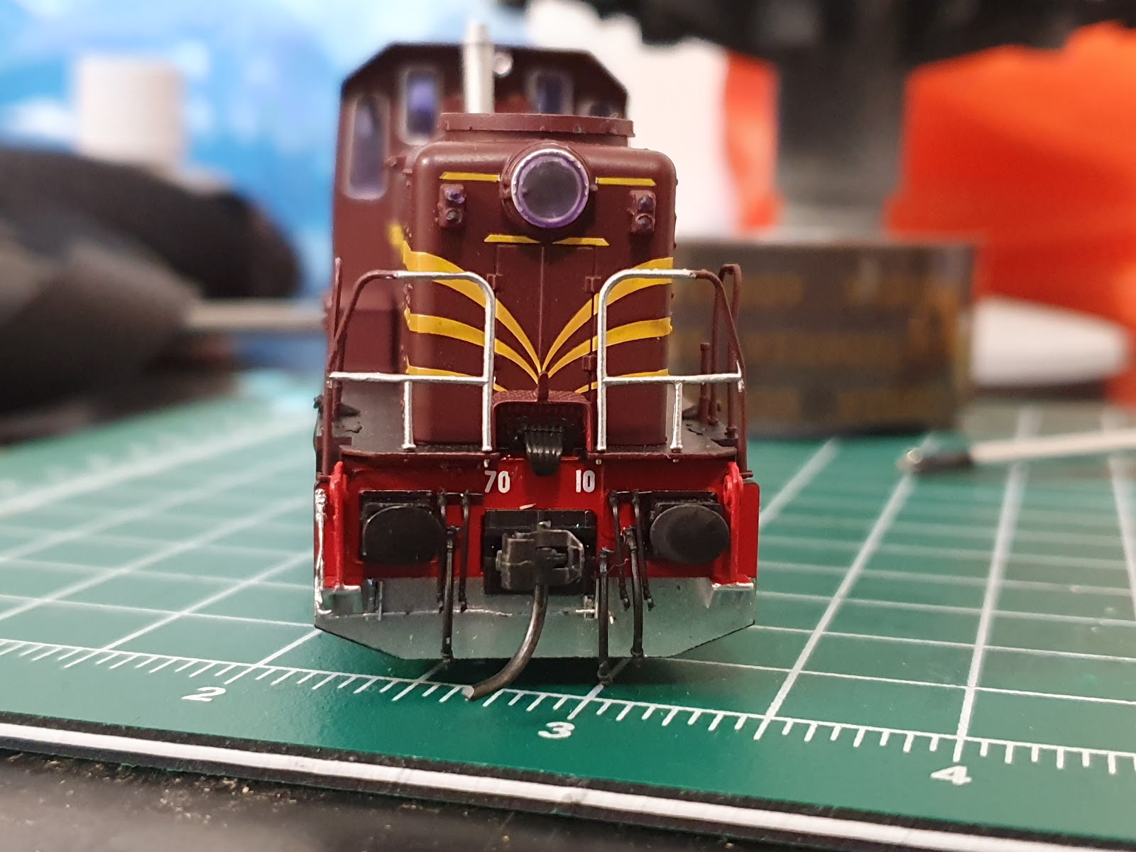
IDR Models 70 Class DCC Sound Chipping and Numbering
First of all the IDR 70 Class is a small locomotive and like the Austrains 30 Class Locomotive you are limited to what DCC Sound Chips you could use, but unlike the Austrains 30 Class Locomotive there is not much butchering to get the DCC chip and speaker to fit. Despite this being a highly detailed model, I was pleasantly surprised on how robust this model is especially with the detailing parts did not want to break off. Little soldering was needed (only the speaker needed to be soldered) and the rest was just plug and play. It was a slightly difficult installation but not impossible to do. Again, this a my way effort.
For the two 70 Class Locomotives, acquired two unnumbered Locomotives and they came with some nice set of decals. I won't go into great detail on how to apply the decals as I have recently already covered that process in a previous blog.
The DCC Sound Chip that is being used here will be a ESU Loksound Micro V4.
The DCC Sound Chip that is being used here will be a ESU Loksound Micro V4.

IDR Models 70 Class that has been disassembled ready for an DCC Sound installation.

An Iphone speaker is going to be used for this sound installation. The brackets that would normally used for this speaker to be installed into 70 will be cut off to allow it to fit in the cab section. Avoid trimming the speaker duct.

The wiring from the plug of the DCC chip went straight into the flywheel of the motor. To remedy this issue, I twisted around the wiring from the chip under the plug. Put the wiring under tension with use of lockable tweezers so it helps it clear the flywheel whilst applying some Krystal Klear to hold in place.

I secure the rest of bundled up wiring with use of some modelling tape. I did have to use some tape for the speaker and output wiring to move it away from the worm gear. The Wiring seen above this fly wheel is not in contact with it.

I drilled in a 1.5 mm hole with a pinvise on the cab floor to feed the speaker wire and output wiring. I decided to keep the output wiring available for potential future use.

Speaker been soldered in and all tested successfully, just about ready for the detailing.


The above photos are more of the process to apply the decals.
7009 and 7010 did operate together on coal train runs to Narellan, therefore the reason I decided go with those numbers.

Narellan Locomotive test running in preparation for the Railway Exhibition
No comments:
Post a Comment