This post continues on with the construction of the roof section of Wingello Waiting Room with Out of Room.
I found that Building the Roof portion of a pitched rood structure that contains an awning can be a bit of a challenge, but I was to somehow to resolve these challenges. I hope this post will be helpful for those who have a desire to scratch build.
Building the Roof
For this part of the build for Wingello Waiting Room with Out of Room, I did come a cross a couple of issues along the way that needed that additional work.
Building the roof on its own without any awnings is easy, but with case of Wingello's Waiting Room model, I needed to construct the awning in a way that it was robust and self supporting. The reason for this is the awning supports which are 3D printouts will not be strong enough to support the awning. Also being part of an exhibition layout, it is going to be moved around and potentially knocked around during transportation to future Exhibition venues. The last thing myself and my fellow Club Members would not like to see is structures showing damage or having to repair structures at an Exhibition event.

Metal Siding Styrene sheet has been measured out and cut into size. The intention is to have a portion of the Styrene Sheet to go into the Roof cavity and be fixed internally so to allow for the outside portion of the awning cover to be self supported.

I had an off cut of Metal Siding Styrene sheet which I used to test out what results would be expected when the roof portion gets constructed. I identified a few issues which were the Metal Siding Styrene sheeting will not be aligned with the roof pitch of the main structure, where the roof met with the Awning cover was not flush and the ends of the Awning cover between the facias and the structure presented an opening. Therefore, some solutions needed to be worked out to overcome these issues.


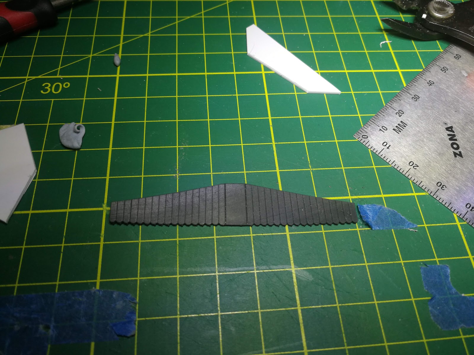
The above two pictures shows two of the solutions being tested out which was to utilise 0.5 mm thick styrene strip that was wide as the thickness of the wall of the building and filing out an angle on where the roof section of the Metal Siding Styrene sheet meets with the Awning cover. This allowed for the styrene sheet of the awning cover to slot under the roof section with a comfortable fit. I later on attached a 0.5 mm strip of Metal styrene sheeting which I cut. I then used this strip to extend the back of the awning where the gaps were showing between the facias and the building. Therefore resolving these issues.

A bit of retro fitting out before construction of the roof.

The Metal Styrene Sheeting is 1 mm thick, therefore I made use of 1 mm x 1 mm styrene strip to join the styrene sheets for the roof together.

I cut up 3 lots of styrene to the profile of the roof cavity. The original intention was mainly to keep the roof shape held together, but discovered that it has actually stopped the flexing of the roof as well as firming up the roof. Looks like not much more styrene will be needed here for now.


I had to introduce a groove that is wide enough to slot in the styrene strip for the fascia.


Bit detailing work done for the rafters.


Guttering detailing work completed.
Late last year, I did some 3D printouts. Here I did the fascia which will fit under the awning from a material called high Black Hi-Def Acrylate. This 3d print material is ok, but I found that only glue that worked was super glue. Basically, I needed to rough up the surface using a tip of a file and attached the styrene strips with Super Glue. Super Glue did provide a reasonable bond, but not a strong bond. Styrene also needed to be attached to also keep the Black Hi-Def Acrylate fascias to stay in a flat shape. Styrene strip also allows the attachment of these facias to the model.


Strips of styrene attached onto the areas that will need other styrene material to attach too. You will see that I taped down one of the 3D Printed facia as it was bent. This helped to keep it flat until the Super Glue cured.


Awning cover just about done.

I also rounded off the edges of the front fascia on the awning cover.

Waiting Room entry detailing completed.


The Awning Supports and the Corbels I also drew up and got 3D Printed in Smoothest Fine Detail Plastic from Shapeways.

Corbels and Awning Support have been attached to the building by using Formula 506 Canopy Glue.


 The above three pictures shows the minor finishing touches which is the top of the roof and awning fascias, the roof capping and the front guttering detailing.


This model of the Wingello Waiting Room with Out of Room is almost completed. Next post will cover the painting of this model and getting it ready to be finally placed onto the Exhibition Layout.


