Monday, 23 July 2018

Exhibition Layout Project- Wingello Waiting Room with Out of Room Part 2

This post continues on with the construction of the roof section of Wingello Waiting Room with Out of Room.

I found that Building the Roof portion of a pitched rood structure that contains an awning can be a bit of a challenge, but I was to somehow to resolve these challenges. I hope this post will be helpful for those who have a desire to scratch build.

Building the Roof
For this part of the build for Wingello Waiting Room with Out of Room, I did come a cross a couple of issues along the way that needed that additional work.

Building the roof on its own without any awnings is easy, but with case of Wingello's Waiting Room model, I needed to construct the awning in a way that it was robust and self supporting. The reason for this is the awning supports which are 3D printouts will not be strong enough to support the awning. Also being part of an exhibition layout, it is going to be moved around and potentially knocked around during transportation to future Exhibition venues. The last thing myself and my fellow Club Members would not like to see is structures showing damage or having to repair structures at an Exhibition event.

Metal Siding Styrene sheet has been measured out and cut into size. The intention is to have a portion of the Styrene Sheet to go into the Roof cavity and be fixed internally so to allow for the outside portion of the awning cover to be self supported.

I had an off cut of Metal Siding Styrene sheet which I used to test out what results would be expected when the roof portion gets constructed. I identified a few issues which were the Metal Siding Styrene sheeting will not be aligned with the roof pitch of the main structure, where the roof met with the Awning cover was not flush and the ends of the Awning cover between the facias and the structure presented an opening. Therefore, some solutions needed to be worked out to overcome these issues.


The above two pictures shows two of the solutions being tested out which was to utilise 0.5 mm thick  styrene strip that was wide as the thickness of the wall of the building and filing out an angle on where the roof section of the Metal Siding Styrene sheet meets with the Awning cover. This allowed for the styrene sheet of the awning cover to slot under the roof section with a comfortable fit. I later on attached a 0.5 mm strip of Metal styrene sheeting which I cut. I then used this strip to extend the back of the awning where the gaps were showing between the facias and the building. Therefore resolving these issues.

A bit of retro fitting out before construction of the roof. 

The Metal Styrene Sheeting is 1 mm thick, therefore I made use of 1 mm x 1 mm styrene strip to join the styrene sheets for the roof together. 

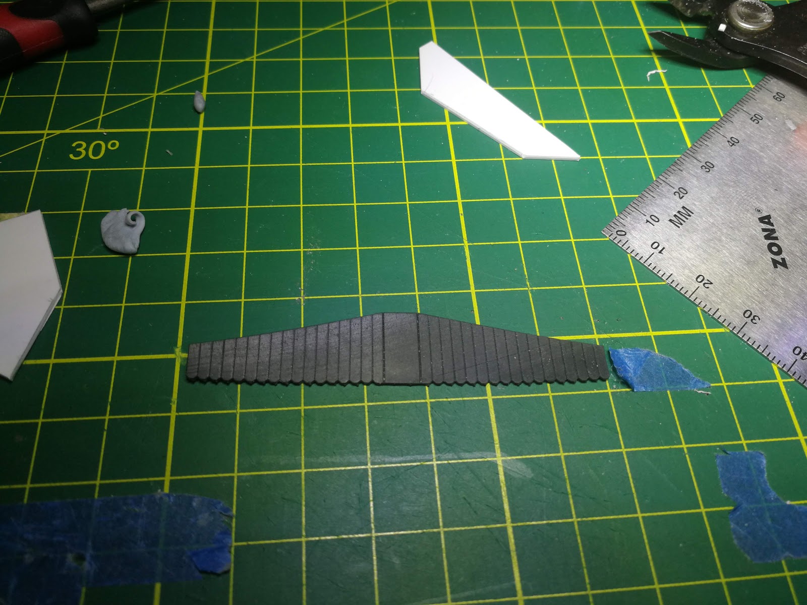
I cut up 3 lots of styrene to the profile of the roof cavity. The original intention was mainly to keep the roof shape held together, but discovered that it has actually stopped the flexing of the roof as well as firming up the roof. Looks like not much more styrene will be needed here for now.


I had to introduce a groove that is wide enough to slot in the styrene strip for the fascia.


Bit detailing work done for the rafters.


Guttering detailing work completed.
Late last year, I did some 3D printouts. Here I did the fascia which will fit under the awning from a material called high Black Hi-Def Acrylate. This 3d print material is ok, but I found that only glue that worked was super glue. Basically, I needed to rough up the surface using a tip of a file and attached the styrene strips with Super Glue. Super Glue did provide a reasonable bond, but not a strong bond. Styrene also needed to be attached to also keep the Black Hi-Def Acrylate fascias to stay in a flat shape. Styrene strip also allows the attachment of these facias to the model.


Strips of styrene attached onto the areas that will need other styrene material to attach too. You will see that I taped down one of the 3D Printed facia as it was bent. This helped to keep it flat until the Super Glue cured. 


Awning cover just about done.

I also rounded off the edges of the front fascia on the awning cover.

Waiting Room entry detailing completed. 


The Awning Supports and the Corbels I also drew up and got 3D Printed in Smoothest Fine Detail Plastic from Shapeways.  

Corbels and Awning Support have been attached to the building by using Formula 506 Canopy Glue.


The above three pictures shows the minor finishing touches which is the top of the roof and awning fascias, the roof capping and the front guttering detailing.

This model of the Wingello Waiting Room with Out of Room is almost completed. Next post will cover the painting of this model and getting it ready to be finally placed onto the Exhibition Layout.


Tuesday, 3 July 2018

Exhibition Layout Project- Wingello Waiting Room with Out of Room Part 1

I has been a while since my last post, but certainly I have been spending the spare time that I have on pushing the completion of my assigned tasks for my Model Rail Club Layout of Wingello, therefore some good steady progress has been achieved so far where we will be nearing the completion of Wingello in the very near future.

Wingello Waiting Room with Out of Room
With one of my previous visits to the NSW ARHS Resource Center, I have found plans reflecting the same but slightly larger variation of the Waiting Room building that on the Down platform at Wingello. The plans states the this type of building as a Waiting Room with Out of Room. The plans reflected Tahmoor, West Bargo, Yerrinbool and Aylmerton Waiting Room structures which seem to have been a longer variation compared to Wingello's Waiting Room facility that is based on the down platform.

Wingello Waiting Room with Out of Room as it stands today.

Tahmoor Waiting Room with Out of Rooms example.


Above two pictures shows inside Wingello's Waiting Room.

Building a HO Version of Wingello Waiting Room with Out of Room
Like the other blogs that I have done for this HO Project, I will post some of the Progress Pictures with a little bit of insight provided. This has been a bit more of a complex Scratch Build Project compared to the Signal Box and the Lamp Shed, but not by a massive margin.

I drew out the dimensions on 0.5 mm clear sheet of styrene. The 0.5 mm clear sheet seen here will be used as a the middle layer of this building. There will be at least 3 layers of styrene sheet to construct the main body, which is for both detailing as well as strengthening up this model.

I also did the same for the clapboard siding styrene. 

 Cutting up completed for now.

Back window has drawn up ready for the the window provision to be cut up. 

Window provision has been cut out and I have placed in one of my 3D printed windows. I took my time in both cutting and filing the opening to ensure it fitted in square as this will be in full view of the public when the Wingello Layout gets exhibited.


The above 3 pictures are self explanatory. Cutting out of the door and waiting room entries on both the clapboard styrene and the middle layer clear styrene.

Here is a bit of a retro fit to ensure that all is going to plan. So far so good. 


I have made use of V-Groove Styrene to reflect the timber walls. I also decided to the internal Framework detailing as well. Here I taken the approach of doing 2 layers of styrene strips so to model the cross bracing details. Yes, indeed a bit of an over kill but I thought why not.


Another session of retro fitting to check on how everything with this model is coming together. So far, satisfied with the results. 

At this point, I decided to do one corner piece of the Waiting Room building. 


On the above two pictures, I have attached the base where I have also attached on the top of the floor V-Groove Styrene siding to represent the timber floor boards. I also scratched built the seating for the waiting room. I will attached the seating later on as it will be painted in a different colour to what the rest of the building is going to be painted in.

The remaining portion of the building being prepared for the final fit out. 

Base of the middle layer was being a slight pain at the base of the waiting room entry. The model of the Waiting Room was square and this portion of styrene would play no critical function, therefore I decided to remove it.

No more of that annoying bit of styrene in the way. I thought it would be a good measure to remove the Out of Room door section middle layer of styrene as well at the base. 

Styrene strips to represent the wooden beam skirting of this building was added. Like what I did with my signal box for this Wingello Layout Project, I have used 0.25 mm thick styrene strip between the clap board siding and the thicker styrene strips. Basically, when the MEK is applied, I find that the 0.25 mm strip reacts well the the MEK and forms a nice neat looking bond between the Styrene clapboard and the styrene skirting.


Door steps and door has also been added and the door frames and Waiting room frames have also been added. Another retro fit out just needed to done to make sure things are progressing well for this build.

Next upcoming post (Part 2) will hopefully see the Waiting Room Shed with Out of Room get completed to the point that it can be painted along with the other buildings for this layout project. At this point of time, I have almost completed the roof section of the Waiting Room Building. The Roof section is something worthy of it own post as it has proven to be a bit more of a complex task that I first anticipated it to be.


Monday, 4 June 2018

Just a Random Post for May 2018 Activities

Wingello Exhibition Layout Project is still moving along nicely. I'm currently working on the construction of Wingello Waiting Room Building, where Im currently mid way in its construction.
But I thought to wait for the next post to which will have more of an update at the near completed stage of the Waiting Room Shed. So I thought I will do a post on other Model Rail activities that I have been involved with.


Over the last Month, I have been involved with running one of the Club Layouts at the St Lukes Church Model Rail Exhibition and have attended the Modelling The Railways of NSW Convention 35 which was held at Loftus TAFE.

Also, I have recently learnt Shapeways has over the last few days announced the name changes of their 3D printing material which has an impact on my Cc1 Models that I have currently placed on the Market.

St Lukes Church Hornsby Heights 31st Annual Model Rail Exhibition
On the weekend of the 4th and 5th of May 2018, St Lukes Church at Hornsby Heights hosted their 31st Annual Model Rail Exhibition where my Model Rail Club was invited to send one of our Exhibition Layouts to take part in this exhibition.

For this event, we decided to take Dunblurtin which is a N Scale fictitious layout based around the Southern Highlands of New South Wales which was constructed back in the 1990's. I assisted in the  operation of this layout on the Sunday of the Exhibition. Despite the age of this layout and with N Scale not having a big following here Australia as compared to HO Scale, we did received more than expected positive comments from the public. And yes, we expect more shows for Dunblurtin to be exhibited at later on this year. I will make note of the upcoming exhibitions where Dunblurtin  and our other layouts that will be on display in future posts.


To finish off the overview of the St Lukes Model Rail Exhibition, it may not compete in size compared to the other exhibitions around NSW, but the organisers has certainly managed to get a few nice layouts into this exhibition over the weekend.


Modelling The Railways of NSW Convention 35
Modelling The Railways of NSW Convention 35 was held at Loftus TAFE back on the 19th May 2018.

I have to give great credit for the both the Organisers and the Presenters for their efforts for making this years Convention a successful one. I would recommend anyone who is looking to do NSW Railway Modelling to attend these events when they are on. I certainly do gain some additional knowledge and inspiration when I do goto these events.

I attended these following sessions:
Modelling the Coonamble Line
Recording Loco Sounds
3D Printing
Corrimal Incline
The World of Arduino

I will be looking to acquire an Arduino Microprocessor in the near future and do some experimentation to determine what the potential uses are for my Tumbarumba Layout as well as Wingello.


 HO Layout of Goulburn

 SDS Models CCA Car Samples to be released in the near future

 Nice array of weathered NSWGR steam and Diesel locomotives


Corrimal Incline Layout

Shapeways Changing the Name of their Materials
I have recently learnt from Rays Bylong Blog that Shapeways have made the bold move in changing the names of some of their 3D Printed materials.

For my Cc1's, the naming has changed to the following:
Frosted Ultra Detail is now called Smooth Fine Detail Plastic.
Frosted Extreme Detail is now called Smoothest Fine Detail Plastic.

Here is the link to my Shapeways Store.
https://www.shapeways.com/shops/branching-out-rail-models