Sunday 24 December 2017

3D Printing

This posts covers some of the 3D items that I have got printed out throughout this year. These 3D printed items are mainly drawn up for my Tumbarumba project.

I will not do a how to do 3D Printing post as there are a few good references on the internet as well as video tutorials on YouTube that explains it better to what I can.

Software for 3D Printing
There are a few 3D drawing programs (paid and free) that are available. The one that I have been using is SketchUp Free, which I have found to be easy to use and provides more features compared to other 3D Drawing Applications that are on the market.

I have been shown another good 3D Drawing Application which that does have better range of features then SketchUp, but it has a huge price tag just to acquire it.

My 3D Printed Projects
Here are a few of my 3D Printed Projects


This is my first project which is a Fireplace. I did this with the  guidance from my Railway Modeller friends. It is designed to fit in a 3 mm flickering LED to simulate a fire. Tumbarumba Station building did have a Fireplace. I have unable to locate pictures or plans for the fireplace at Tumbarumba, so I have modelled the one that is still in existence in Oberon Pc3 Station Building.


Above two pictures is a 3D print out of the Tumbarumba Chimney.


I also printed out the Roof Capping and the Finial.


3D Printed Base with scales, next the the Weight Bridge Office.


Tumbarumba Station Sign done both in Frosted Detail 3D and in Brass.


The above is the CC1 Water Closet with Lamp Room 15" Precast Panels (which once resided at Tumbarumba). This has turned out better than what I have expected. I will be working on making these available on the Shapeways 3D Store early in 2018. More details on this model will be provided once it fit to goto market.


Internal detail of the CC1 3D Printout.

Merry Christmas
I would like to wish my followers and viewers of my blog a Merry Christmas and wishing you all the best for the new year.


Saturday 16 December 2017

My First Scratch Built Structure

Just thought to have a short break from my series of posts on Tumbarumba Station Building Kit Bash, as I do want to present posts for other projects that I had running in parallel.  Well one of the upcoming posts involves the manufacturing some of the detailing for Tumbarumba Station Building, so in a way not stalling on the updates on that front.

Over this year, whilst waiting for other supply of items that were needed to move forward with the Kit Bash activity, I decided to get started on one of the Scratch Building projects just to keep things moving forward.

When I decided to model Tumbarumba, I set a personal challenge for myself to try and make it as prototypical as possible. This meant if a line side item could not be acquired from the market place, then I would need to somehow manufacture it myself.

As being new to this level of modelling, I had to learn how to construct the required items.

This means building item from scratch using materials such as styrene to the more modern day method of modelling, 3D Printing.

Thankfully, the Model Rail club that I am part of has a good mix of talented Railway Modellers who were more than willing to educate me in these methods of Modelling.

Hopefully this post will be helpful for someone out there who wishes to get initiated into some scratch building activities. I have personally found that this Project is one of the best examples to get initiated with scratch building.

My First Scratch Building Exercise (Weigh Bridge Office)
First of all, during my researching, I was only able to find one picture of Tumbarumba Weigh Bridge Office which was a distant background object in a photo. It was the older style cladded weatherboard type, not a Precast Concrete Weigh Bridge Office to the likes of the one based at Bombala. This was a bit of a surprising find, but found out later on that the cladded weatherboard type of Weigh Bridge Offices were a common sight at locations where both 10" and 15" Precast Station buildings resided.

I sourced the plans for this scratch build exercise from the NSWGR 20 Ton Weigh Bridge and Pit Greg Edwards Data Sheet G7. This Data Sheet contains three different examples of the Cladded Weatherboard Weigh Bridge Offices.

With the limited information I had on Tumbarumba Weigh Bridge Office, I concluded that I needed to model a version that combines both the Queanbeyan and Wauchoupe examples that were detailed in the Greg Edwards Data Sheet G7.

From the Data Sheet, I determined that I needed the following items:
- Evergreen 4061 Clapboard Styrene Sheet (1.5 mm Spacing, 1 mm Thick) for the Wall Cladding
- Evergreen 4526 Metal Siding (1 mm Spacing, 1 mm Thick) for the Roof
- Evergreen 111 Styrene Strips (0.4 mm x 0.75 mm) for the Door Frame
- Evergreen 120 Styrene Strips (0.5 mm x 0.5 mm) for the corner studs
- Evergreen 123 Styrene Strips (0.5 mm x 1.5 mm) for the detailing of the Roof and window framing
- Evergreen 124 Styrene Strips (0.5 mm x 2 mm) for the fascias and the Roof Capping
- Evergreen 142 Styrene Strips (1 mm x 1 mm) for the lower Window Frame detailing and internal frame detailing
- Evergreen 153 Styrene Strips (1.5 mm x 1.5 mm) for the Centre Beam between the Windows
- Evergreen 219 Styrene Rods (0.64 mm) for the Roof capping detailing
- Plastruct 90502 Styrene Angle (1.6 mm) use as a bracket inside to hold in the door
- Grandt Line 30" x 66" Planked Door HO Scale (Reference Number 5293)
- Grandt Line 12 Pane Window HO Scale (Reference Number 5009)

Note: I will do my best to describe the technical names of the components for this structure, I had to rely on Google searches to get the name of each component.

Some of the Tools that will be mentioned in this post:


- Zona Triangle (Purchased from Australian Modeller https://www.australianmodeller.com.au/collections/tools/products/zona-zo-37433-3-triangle)

- Nibbling Tool (Purchased from Jaycar https://www.jaycar.com.au/nibbling-tool/p/TH1768)

- Fiskars Soft Grip Rectangle Hand Punch (Purchased from Spotlight https://www.spotlightstores.com/craft-hobbies/paper-craft/cutting-tools/punches/fiskars-soft-grip-rectangle-hand-punch/p/BP80295454)

I will not be mentioning the Zona Triangle much in this post, but I found it to be a handy tool to use to keep items such as walls squared up when they have been glued up.

I also decided to design my own 3D print outs for the base and a 6 pane window frame. More details on this will be in an upcoming posts for 3D printed models.

Before going into the details for construction, here are a couple of examples of Weight Bridge office that are still in existence today.


The above 4 photos are of the Weigh Bridge Office that has been preserved at Gundagai that I photographed back in November 2017.


Above photo is the Bowral Weigh Bridge Office that has the similar window configuration to the one that I going to model for my Tumbarumba Layout. Unfortunately, for this example the windows have been boarded up. I took this photo back in October 2017.


Focusing back on the actual scratch build, there was a simple task to cut up of the Clapboard Styrene Sheet. Basically I drawn up the area on the styrene that was needed to be cut up.


I used Blu Tack to do a test build to see how it all turned out.


At this stage I had receive my 3D Printed base for the Weigh Bridge Office. I have cut up the front Clapboard panel to size to provide the provision for the window frame.  The Grandt Line 12 Pane Windows are seen in the lower picture.

The Clapboard Styrene Sheet is 1 mm thick and to allow for the corner studs (which are the 0.5 mm x 0.5 mm Styrene strip) to fit flush with the Clapboard, I file out a 0.5 mm x 0.5 mm channels into the side edges on the none detailed side of the Clapboard cutouts for the front and rear walls.


You see another Window Frame that I got 3D Printed as per the dimensions provided from the Greg Edwards Data Sheet G7. To cut the area that I needed for the window, I made use of a Nibbling Tool that I purchase from Jaycar Electronics. The Nibbling Tool was suggested by one of my Model Rail Friends in the Club that I am part of. Certainly provides a nice straight clean cut.


The door way was cut out with the combined use of a Fiskars Hand punch which I acquired from Spotlight and the Nibbling Tool. The Fiskars Hand Punch was again another recommendation from one of my Model Rail Friends in the Club that I am part of.

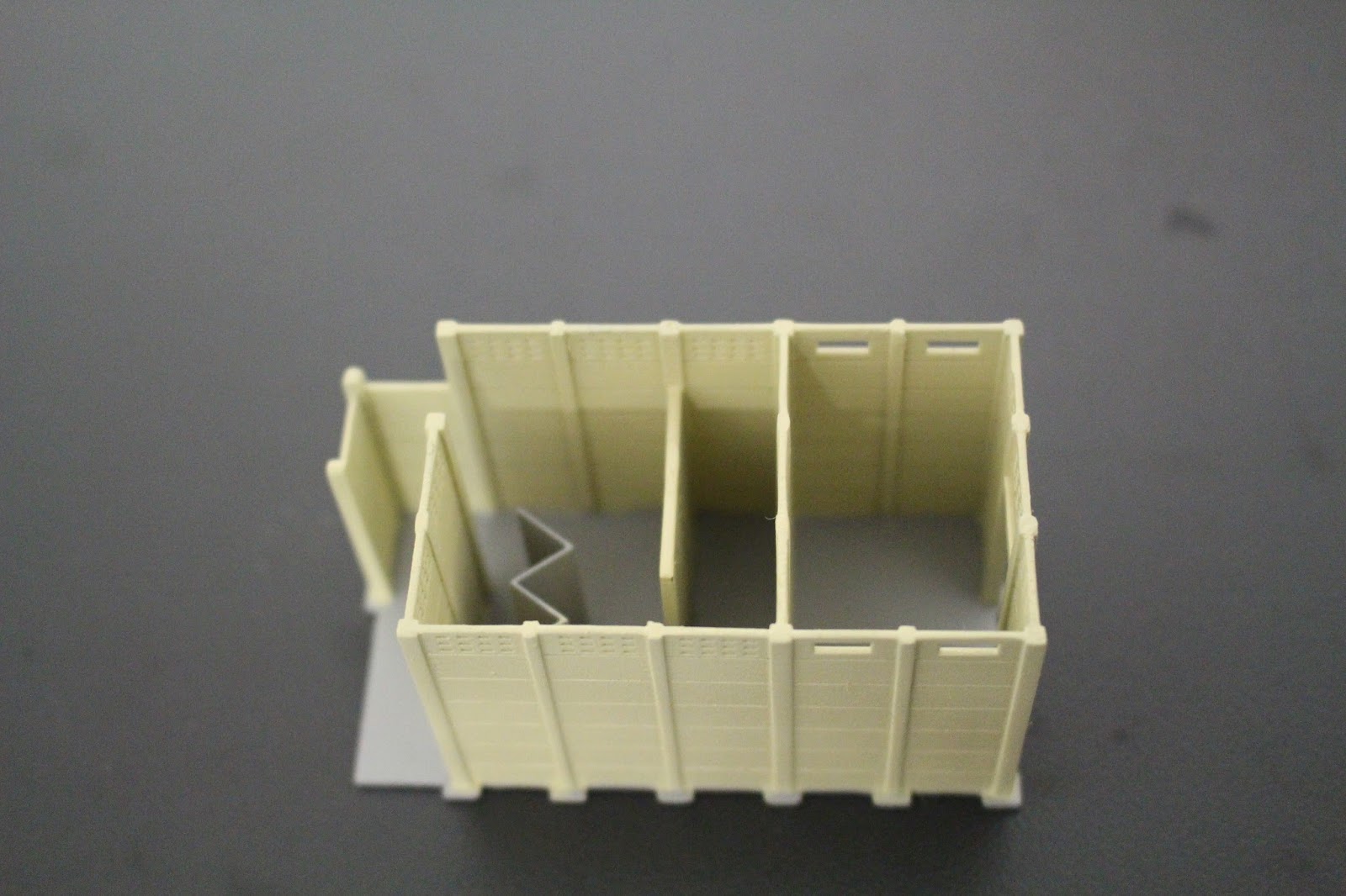
I used the 1 mm x 1mm Styrene strips in the inside corners when gluing up the walls of the Weigh Bridge Office. I feel that by doing this, it allows for a stronger bond where the walls join up.

For the construction of the window frame. I first got a length of 1.5 mm x 1.5 mm styrene strip (for the centre beam of the window frame). I then filed out a 1.5 mm wide and 0.5 mm deep grove at one end of the strip so to allow for the 1.5 mm x 0.5 mm Styrene strip (to make up the head casting of the window frame) to be fitted in flush with the centre beam of the window frame and then glued them together.

The 2 x Grandt Line 12 Pane Windows were carefully glued into the window frame work that has been already constructed. I completed the remainder of the frame work on the edges (the side casting of the Windows) of the 12 Pane Windows with 1.5 mm x 0.5 mm Styrene strip, then trimmed off the overhanging styrene.

The great thing about this project is that the Grandt Line 12 Pane Windows are the same size to what is represented on the Greg Edwards G7 Data Sheet. The window frame fitted nicely to the model. To finish off the window fixture, I used a strip of 1 mm x 1 mm styrene to make the sill of the window frame. I fixed the strip for the Sill parallel onto the top of the lower section of the Front Lower wall overlapping 0.5 mm of the strip which will later on assist to secure the completed window frame to the model.


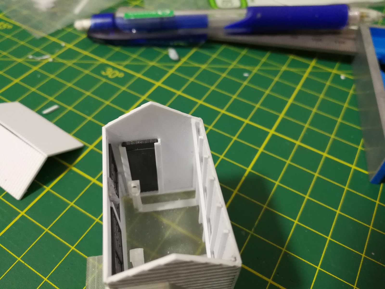
I made a late decision to do a bit of detailing of the framework inside the Weight Bridge Office.This was more so to show a bit of internal detailing due to the size of the windows. This was done with 1 mm x 1 mm Styrene strips and placed them as detailed in the G7 Data Sheet. Would have been certainly better if I did that before assembling this model. Also worth mentioning that I left a 1 mm space from each the strips that was used in the framework to the base of the model to allow for the model to fit onto the 3D printed base.

I have used the angled styrene to allow for the Grandt Line Door to be fitted into the model and fitted the remainder of the Clapboard at the top of the Window frame. The reason I have used the angled styrene is to allow the door to be slotted into the model. The G7 Data shows the door to be narrow in width. The angled styrene help give the Grandt Line door that narrow look when looking from the outside in. This also removed the need to cut the Grandt Line Door into a narrower width.

The corrugated Roof Section was cutout to size then glued onto the model.


The detailing of the Facias, Roof Capping, the door frame and door step was added.


I have Primed the model with Tamiya Primer and Painted the model with the following Colours.
- Humbrol Ligh Grey (for the roof)
- Model Masters Light Ivory Enamel
- Tamiya White Acrylic X2 (for the window frames)

I also used the Testers Dull coat once the painting was completed.

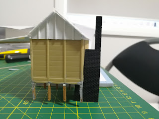
This model is not 100% completed yet as I do need to do the window glazing, paint the door and attach the guttering. The Weigh Bridge Table needs to be also manufactured (which is currently work in progress), but at the very least I can say that the main body of the Weigh Bridge Office is completed.


On a final note for this Scratch Build above are two more views just to show the detailing such as where the framework ends to allow the fitting of the 3D Printed Base. How the facias and the strip for the window Sill fits to this model. And demonstrates how the Grandt Line Door slots into the angled styrene within this model.

The next upcoming post will be covering the 3D Printed Items that I produced which will include the Base and 6 Pane Window Frame for this Weigh Bridge Office.

Saturday 9 December 2017

Tumbarumba Station Building Kit Bash Part 5

Corrugated Awning Cutout


This post is mainly focused on modifications that are done to the base of the Station Building plus a little more on the minor detailing that has been added. But before I move onto that topic of the base, I just wanted to show that I did a cut out of the area of the corrugated styrene that was needed for the awning.

More detail of the awning construction will be covered in a future post as at the time I felt it was best to place the remainder of the awning construction into the do it later on basket.


Base of the Station Building Modifications


With the first part of the modification, I have kind of followed the directions that are detailed in the Australian Journal of Railway Modelling Number 11, where code 55 track was used to model the rail line that was utilised as a bearer on the base of the building together with an array of concrete stilts. The kit does come with a supply of the concrete stilts that are designed with a tongue that lines up with the the square slots on the base of the building.

I did use these few words kind of followed in my last paragraph and now for me to explain where I was heading with that point.

In the Australian Journal of Railway Modelling Number 11, it modifies a Rail Central Pc3 Station Building Kit into a Pc2. It points out in the article that the 15" Panel Pc Buildings had the rail inverted on the base of the building (as in my picture above) where as the later Versions of the 10" Panels had the Rails rested on their side between the stilts and the base. That same article showed photographic examples of Conoble Pc2 (10" Panel) station that clearly show the Rails rested on their side.

As Tumbarumba Station Building was an early version of the 15" Panel Pc Building, I used the inverted rail method with Micro Engineering Code 55 Track.

Before sticking the track onto the model, I marked the area where the concrete stilts are to be attached and filed the edge of the track with the width of the concrete stilts. Reasons for that will be coming up soon in this post.

I used ZAP CA glue to stick on the rail onto the base of the model. I have found that ZAP CA glue has done a great job in sticking metal rail onto the plastic base.


With the concrete stilts, I removed the tongues with a hobby knife and cleaned up the cut with a file. I then I cut up a strip of styrene to make up the extended length that is needed to cover the area of the rail. I trimmed the excess styrene on the concrete stilts with Xuron Track Cutters which help lined up the styrene with the remainder of the concrete stilt. This was repeated many times.


Back to one of my earlier points in regards to filing the edge of the rail to the area where the concrete stilts are being placed. The reason for this is that the base of the rail is just too wide to allow for the modified stilts to be placed over the rail. Basically without the modification to the rail the styrene portion of the concrete stilt will spread out. When the rail gets filed, it allows for a good fit which also allows for the concrete stilt to be glued onto the model without the stilt looking crooked or distorted. It was fortunate for me that I tired this out before gluing the rail line onto the kit as it would have been a messy task to have resolve that issue.

The stilts were glued onto the Station Building Model by use of a Shellys Araldite.


After gluing on all of the stilts, I used Tamiya Putty to fill in the gaps around the base of the model. Does look a bit rough, but fortunate in a way that the Station seat and the platform will cover some of that up. Still will need to do a bit of cleanup work before painting this model.

Minor Detailing Work
You may have also noticed in the above progress photo, I have placed in an electricity meter box between the windows of the Station Building. This was constructed with a a bit of wiring to represent the electrical wiring and the Meter Box was made from a rectangle styrene tube with a bit of styrene sheeting cut to size to make up the hood. 


Around to the back of the Station Building. I have done the window framing of the Extended portion of the Station Building. Also take notice of the area where the second last panel section to the left of the building that there is a stilt missing and a hole drilled into the side of the building. This is to allow for a Fireplace with a 3 mm Flickering LED and a Chimney to be installed.

Tumbarumba was one of a few PreCast Station Buildings that was provided with a fireplace. Batlow and Oberon Pc3 Buildings were the others that had a fireplace installed.

One further item to note that from the photos that I have seen of Tumbarumba, it seems not to have the corner bracing on the stilts (bracing was also mentioned in Australian Journal of Railway Modelling Number 11). Though, I have only seen the later photos of the back of Tumbarumba Station Building in its final few years of existence, so therefore can not see the need to place them onto this model. Meaning that I have not been able to confirm if the bracing was ever fitted.

To close this post off, another reflection of hindsight is needed. From this experience, I would recommend that the stilts should be one of the last item to be done if you are going to kitbash a Rail Central Pc Building. I guess the same applies to other building projects that contain stilts at the base. The reason for this, I accidentally broke some of stilts off whilst doing other modifications to this kit. The main offenders are the corner stilts. Hopefully, this issue will be resolved once this Station Building is finally fixed to the layout.

Sunday 3 December 2017

Tumbarumba Station Building Kit Bash Part 4

Outside Seating

Tumbarumba had outside seating that was fixed to the Station Building. This seating arrangement seemed to have been unique to Tumbarumba, but have fit the design to what was used within the Shelter Shed portion of the Pc Building.

Please excuse my ignorance on the terminology of the various components that make up this type of seating, but will do my best to describe each item. I believe that similar types of seating are used in Churches which are called Pews, but not sure if the railways adopted the same terminology. However, more than happy to be educated on that point.


On the Greg Edwards Data Sheet for Station Buildings Standard Designs Pc1 and Pc2 (Data Sheet B27),  it contains the outlining of the seating frame. I photocopied that portion of the Data Sheet and carefully cut the profile. By use of Blu Stick glue (or a glue stick that is used to stick paper to cardboard), I glued on the cutout to a strip of styrene. Then cut around the outlining of the seating frame, then cleaned it up with a file.


This process got repeated a few times as four of the of these seating frames were needed. I also placed each of the seat frames side by side, clamped them together so I could file them to be consistent to one another.


From the photos that I have seen of the seat at Tumbarumba, it had length of timber which I assume would have been used for the bracing. I have modelled this out of a strip of styrene to reflect this bracing. Note that the seat frames were attached to the vertical Precast Concrete Posts.


Once the bracing and the seating supports were glued up, the remainder of the seat detailing was carried out.


I made use of the Xuron track cutters to trim off the excess lengths from the styrene strips that were glued onto the model of this seat. I found that the Track cutters did provide a nice clean cut.

Toilet Door Foot Steps


I had to manufactured the door steps for both of the doors from the extended part of this Pc2 Kit. This was again done with styrene strip which I rounded off the edges with the file.

Before moving into the next topic, take note of the fine strip of Styrene that was added to the edges of the end wall. This was put in place in order to allow for alignment with the other Precast Concrete posts on this building.

Corner Precast Concrete Posts


I manufactured the Precast Concrete Posts from 1.5 x 1.5 mm strip of styrene. As like the real Pc building a slot in the middle of the Precast Concrete posts was produced with a finer strips of styrene either side.


Here is a moment of hindsight where I should of removed all of the Corner Precast Concrete post on this kit and applied the same modification of what was done at the other end of the building. However, I scribed in a line to represent the slot.

Interior Walls
Reason that I would like to detail the interior walls is that I do want to open up some of the doors once this Building gets completed and placed onto the layout. I'm also going to later on place in some lighting which will show some of the detailing inside the building. If the doors were going to be locked and no lighting placed in this building, then I would have not have carried out this modification.


The Pc2 Rail Central Kits is supplied with only one internal wall which only contains detailing on one side. Therefore I have scribed the lines to represent the 15 inch concrete panels. The circles that are seen on the non detailed side of the model should not be an issue as there will be obstructed with other items placed in front of them. The supplied internal wall would be normally placed between the Shelter Shed and the office with the detailed side facing the Shelter Shed.


I manufactured another precast internal wall all out of styrene which will be placed between the Shelter Shed and extended toilet sections of this building. Detailing of the Precast 15 inch panels were scribed in.


I utilised the internal wall from the Second Pc2 Kit where it is going to be placed between the Office and the Living Room. I have modified it to have a door and also scribed the lines to represent the 15 inch panels. I have also placed in a door frame made from Styrene strips.

Roof Section
Form my last Blog post, I focused mainly on the roof section modifications that were needed to be carried out to get the high pitched roof version of a Pc Building. This part is a continuation of the roof modifications.


As mentioned in Tumbarumba Station Building Kit Bash Part 3, the top narrow row of panels were needed to be removed. Here I have replaced that row with the with 1.5 mm x 1.5 mm styrene strip which now better represents the lower Beams of the roof that the rafters would have adjoined too.


As you may noticed that I have attempted to utilise the one gable for the detailing of the vertical strips, but the results did not look good at all. So I manufactured a another separate gable with a thin sheet of styrene.


This resulted in a better look for the model as the Gable sheet overlapped were the cut was made to remove the original Gable, also making it look more prototypical.


With the gables and the lower beam for the rafters now sorted, I was able to get the dimension that were needed to make the ceiling as well as the support for the roof.